Rental House Management System: Thesis Documentation Chapter Five
CHAPTER 5: SYSTEM DESIGN
In this chapter, the system design will be demonstrated. It will focus on showing conceptual and physical design of the databases and the user interaction with the system using the Unified Modelling Language (UML) diagram called Use Case Diagram.
5.1. CONCEPTUAL DATABASE DESIGN.
Conceptual Design is the first stage of design in which the drawings are the dominant tools and products. The purpose of the conceptual design phase is to build a conceptual model based upon the previously identified requirements, but closer to the final physical model.
In this case the conceptual design model used is the Entity-Relationship (E-R) Diagram. It shows in a nutshell the relationship between the entities and their attributes.
Figure 4 shows two entities user and transaction for Tuma pesa Database
Figure 5 shows eight entities namely, tenant, house, payment, contract, tenant-in, tenant-out, user and contacts for Rental House Management System Database.
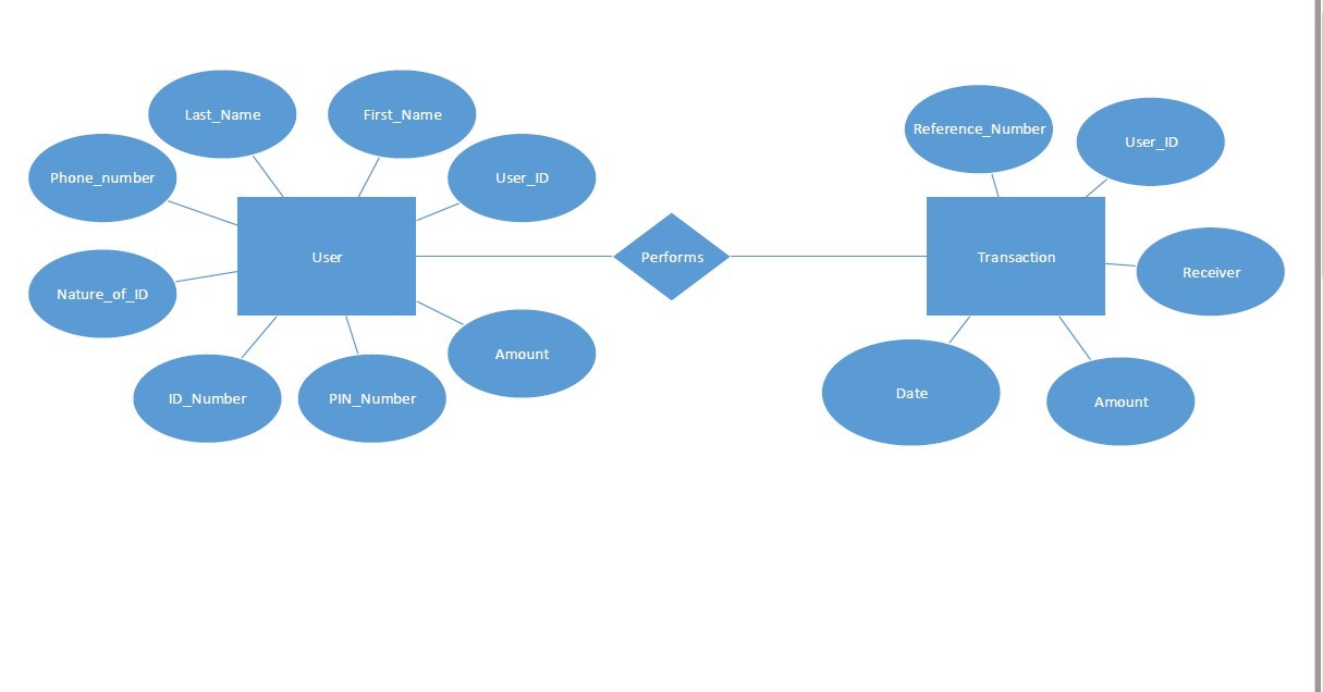
Figure 4: Tuma Pesa Database.
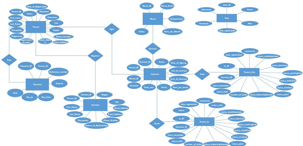
Figure 5: Rental House Management System ER Diagram
5.2. PHYSICAL DATABASE DESIGN.
This is translates the logical data model into a set of Structured Query Language (SQL) that define the database. The entities become the tables, attributes become the columns and relationships become foreign keys.
The figures below show the physical database designs for two databases involved in this system namely: tuma_pesa and rental_house databases.
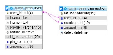
Figure 6: tuma_pesa database physical database design
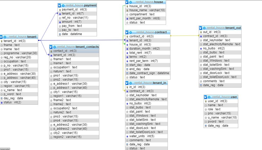
Figure 7: rental_house database physical database design.
5.3. USE CASE DIAGRAM.
Use case diagram is a UML diagram that representation of a user's interaction with the system that shows the relationship between the user and the different use cases in which the user is involved. It shows relationship between use cases, relationships and actors. These actors can either be internal or external agents or both.
In this system, there are three actors two are internal agents and one external agent. The internal agents are the system administrator and the manager while the external agent is the tenant.
The diagram below shows how the actors integrate with the system.
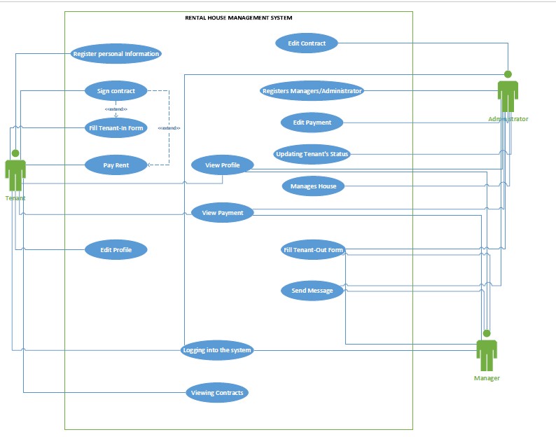
Figure 8: Rental House Management System Use Case Diagram.
Rental House Management System: Thesis Documentation Abstract and Table of Contents
Rental House Management System: Thesis Documentation Chapter One
Rental House Management System: Thesis Documentation Chapter Two
Rental House Management System: Thesis Documentation Chapter Three
Rental House Management System: Thesis Documentation Chapter Four
Rental House Management System: Thesis Documentation Chapter Six
Rental House Management System: Thesis Documentation Chapter Seven
Rental House Management System: Thesis Documentation Chapter Eight
Rental House Management System: Thesis Documentation APPENDIX A
Download the source code of this Thesis:
Rental House Management System